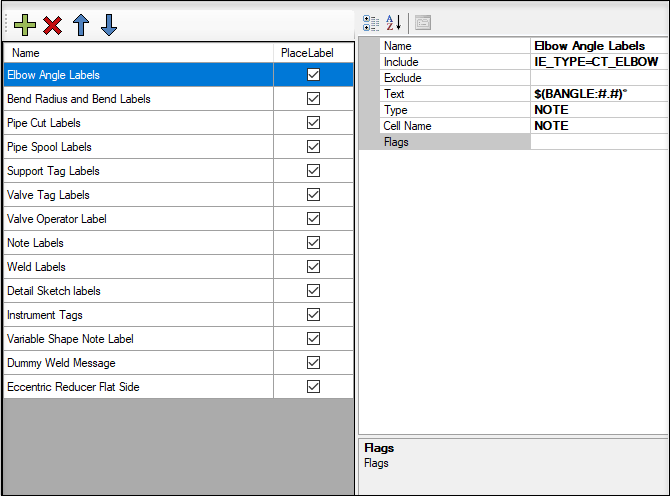
Isometric Style Configuration - User Labels


When finished making any changes in the fields, click Save on ribbon to apply the changes.
Flag Options for User Labels
Below are a list of flag options available when defining User Label modifications.
| Setting | Description |
|---|---|
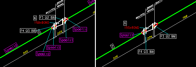
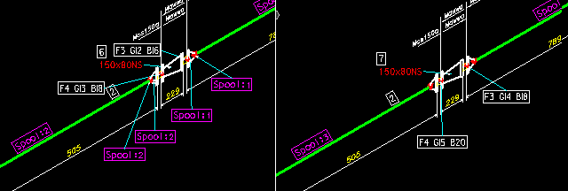
| S | Displays the user label only once for a spool. |
| P | Displays this user label only once for a pipe cut (sequence of pipes/bends). |
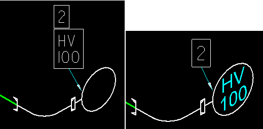
| I | Place the label text in the component cell instead
of a separate label.
An option is offered to place the content of a user label inside a component cell. An example of this is shown below where an instrument tag is to be displayed within a gauge symbol. |
| E | Apply the user labels to existing components as well.
Normally the INCLUDE/EXCLUDE rules only operate on NEW components. Those that are listed on the BOM and existing components are not included in the basic selection set used for user labels. You can however force them to be included by adding an E to the flags field. |
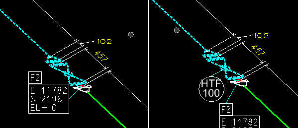
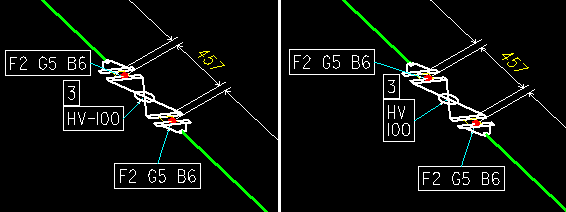
| - (Hyphen) | Any hyphen in the label text will be interpreted as
a line break.
This indicates the label routines to interpret hyphens in the label text portion as a text separator. The text part can then either be distributed among different fields in the label or displayed in a multi line fashion. This is specifically for tags like HV-100 that need to spread over two lines, one with HV, the other with 100. |